Dismantling the V2
As the redevelopment of the Memorial takes place, we are in a unique position to include stories that have not yet been told at the Australian War Memorial. The V2 rocket and Meillerwagen trailer tell the stories of Australian bomber crews that fought to defend the Allies against V2 attacks, those forced to work on V2 factory lines, the casualties of V2 bombing raids, and the connection between V2 rockets and the Space Race.
In order for these items to be displayed, they need to undergo conservation assessment, treatment and repair.
Due to extreme corrosion (image 1), the rear bogie (undercarriage)(image 2) had to be removed to stabilise the Meillerwagen to move it safely from storage to the conservation workshop. A stand was manufactured to support the spine of the Meillerwagen in order to remove the bogie. The bolts and caps were removed with the support of a forklift. Once free, the bogie was lowered onto dollies and wheeled out from under the Meillerwagen. It is currently supported on a frame and conservation treatments are being considered (image 3).
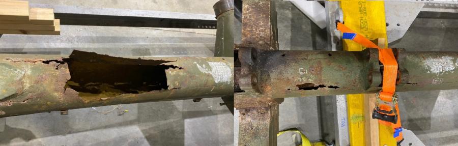
Image 1: Severe corrosion
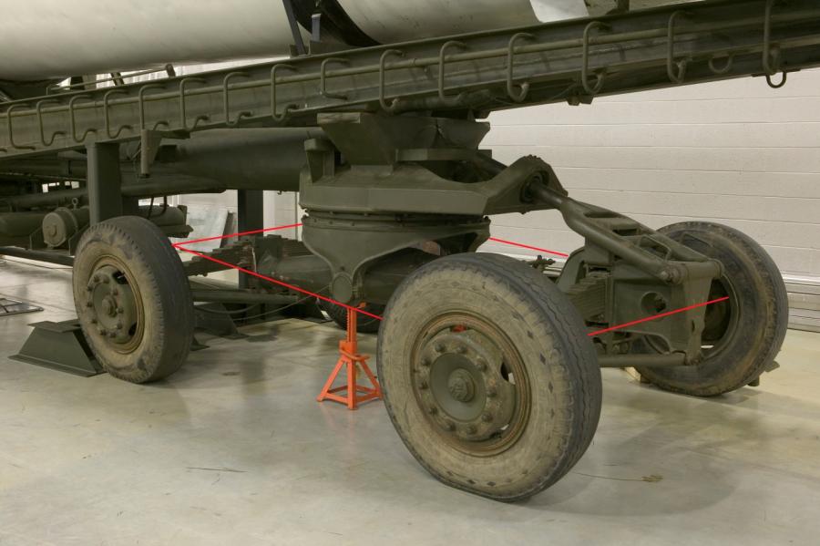
Image 2: Bogie attached to Meillerwagen before removal.
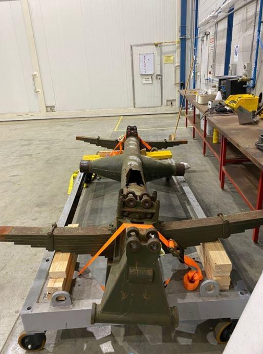
Image 3: Bogie supported on frame
The Meillerwagen was retrofitted with a new axle, wheels and tyres. Four U-bolts were welded to the axle to locate it in its correct orientation; two push tabs were welded on as towing points (image 4). The axle was then fitted using the original bogie caps; the wheels, fitted with new tyres, were attached; and the Meillerwagen was lowered to the ground.
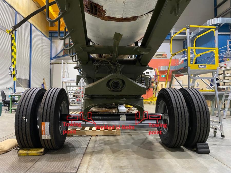
Image 4: New axle, wheels and tyres attached to the Meillerwagen
New tyres were chosen after examining Second World War photographs and films of Meillerwagens, which showed tyres using a variety of different treads. Tyres were also fitted to the original wheels from the bogie and to the original wheels attached to the front sprung axle of the Meillerwagen, replacing the degraded non–original tyres (image 5). Now safe to move, the Meillerwagen was carefully towed from storage into the conservation workshop for surveying, investigation and conservation.
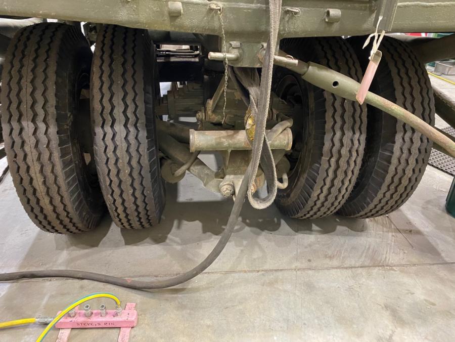
Image 5: New tyres fitted to front sprung axle wheels
Elements of the V2 structure were missing or damaged due to corrosion mostly formed during the 1940s and 1950s. Parts of the interior were left after manufacture in bright mild steel form with no paint to inhibit corrosion. This explains why areas of the V2 have been corroding from the inside out. Glass wool, used as insulation against heat, left behind the skin had created a water trap, shortening the life of the skin and internal rocket components (image 6). The V2 needed to be dismantled to fully inspect the level of damage and determine conservation requirements.
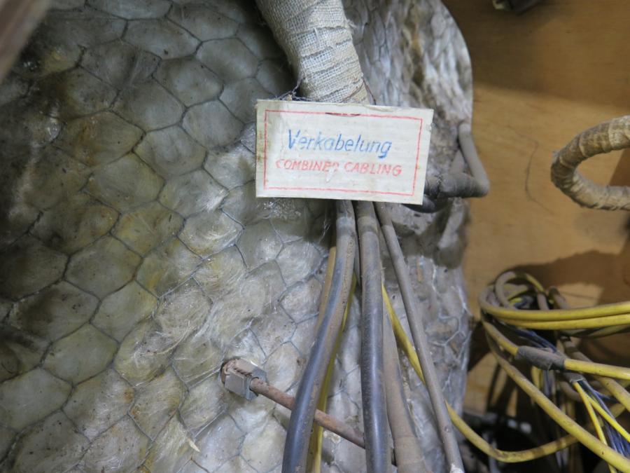
Image 6: Interior image of control compartment showing glass wool and German/ English label.
Our method for dismantling the V2 was based on how the rockets were assembled in factory lines: with the removal of the tail section, engine, warhead, control compartment, and finally the centre section. The tail, engine and centre sections will all be placed on custom manufactured stands for easy access and mobility.
While inspecting the V2 a number of paper tags were found naming different parts of the rocket in German and English. These were likely placed during Operation Backfire – part of the Allied attempt to acquire German technology which took part in during and after the Second World War. These tags were documented and safely removed, retained and sent to the paper conservation team for treatments before being placed into storage (image 6).
To begin dismantling the V2, the top metal strap with felt lining between the centre section and tail section was removed to gain access to the bolts connecting the tail and centre sections (image 7). The bolts were assessed to see if they could be used to support the forward section of the tail section on its stand while disassembled. Three bolts had been broken, most likely when the V2 suffered a break almost 50 years ago, but the rest of the top bolts holding the tail section to the centre section came loose with lubrication.
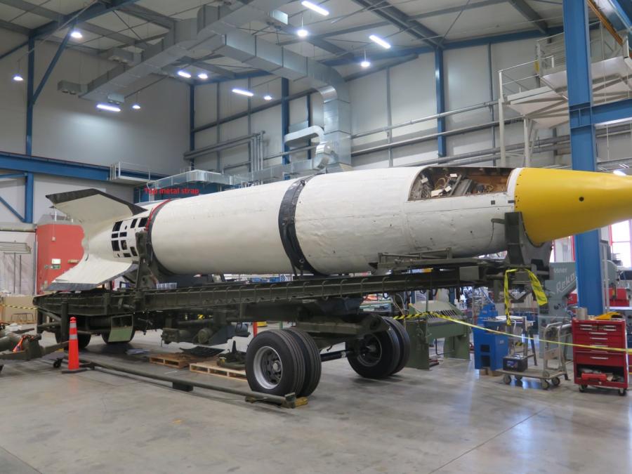
Image 7: V2 and Meillerwagen in conservation workshop
The bottom of the tail section had weakened and folded in on itself due to corrosion. The metal on top had stretched with folds in the surface skin occurring due to this collapse.
A temporary stand with wooden formers covered in ethafoam was made to support the tail section (image 8). Asbestos material along the control vane mounts was sealed with a PVA and water mix (image 9).
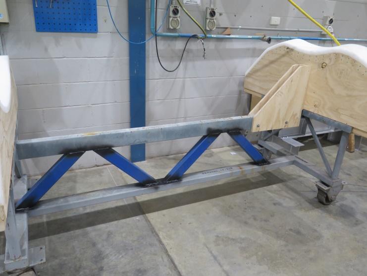
Image 8: Temporary frame for tail section
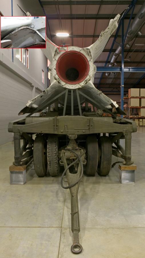
Image 9: Control vane mounts – asbestos material sealed with PVA and water mix
The external steam and exhaust pipe coverings were removed and safely stored to remove the pipe locking rings. The top steam pipe exhaust cavity was found to have a significant amount of debris, mainly remnants of wasp nests. Loose iron corrosion scale was littered on surfaces of the exterior panel. The debris was removed with a brush and dustpan (image 10).
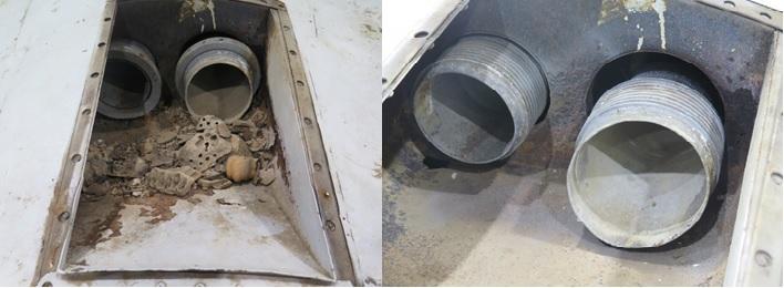
Image 10: Steam exhaust pipes with lock rings fitted and debris (left); debris cleared and exhaust pipe lock rings removed (right)
The exhaust pipe lock rings had suffered due to exposure. Previous attempts to remove the rings showed holes drilled around the perimeter of the ring (image 10), which were also distorted from being struck. Removal of the rings involved repeatedly applying heat to the ring with a hot air gun and applications of Rost Off to all surfaces. However, only 20 mm movement was achieved. Both rings were seized in place due to internal thread corrosion build up. The rings had a slot cut into the outside edge and were pried apart with a screwdriver tip struck with a hammer to release ring thread. Rings were successfully removed, labelled and will be repaired (image 11).
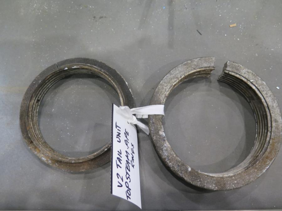
Image 11: V2 tail unit top steam exhaust pipe lock rings after removal.
The underside steam exhaust pipe and ring was found to be in comparatively good condition and was easily removed with a C-spanner. The locking ring was labelled and stored safely (image 12).
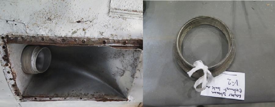
Image 12: Single steam exhaust pipe with lock ring removed.
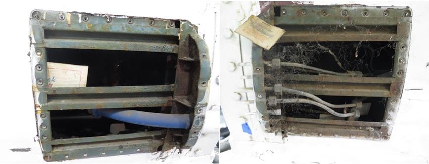
Image 13: Left side cowling removed; right side cowling removed; paper tags found behind both cowlings
The left and right side cowlings were removed to detach internal piping from the engine. All internal piping was found already disconnected. More paper tags were found attached to internal components of the combustion unit. These were documented and removed for safe storage
The adjustable rod on the Meillerwagen affixed between the rear V2 mount clamps was removed in order to loosen the V2 mount clamps. Split pins, nuts and locating pins were removed from left and right hand sides of adjustable rod (image 14). These had to be released by levering with considerable force with pry bar and copper head mallet (image 15). Mount clamps were levered with a pry bar to roll away from the upper section of the V2 (image 16).
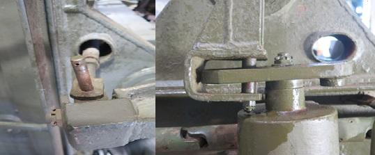
Image 14: Rocket mount clamp pin removed (left); rod arm completely removed (right)
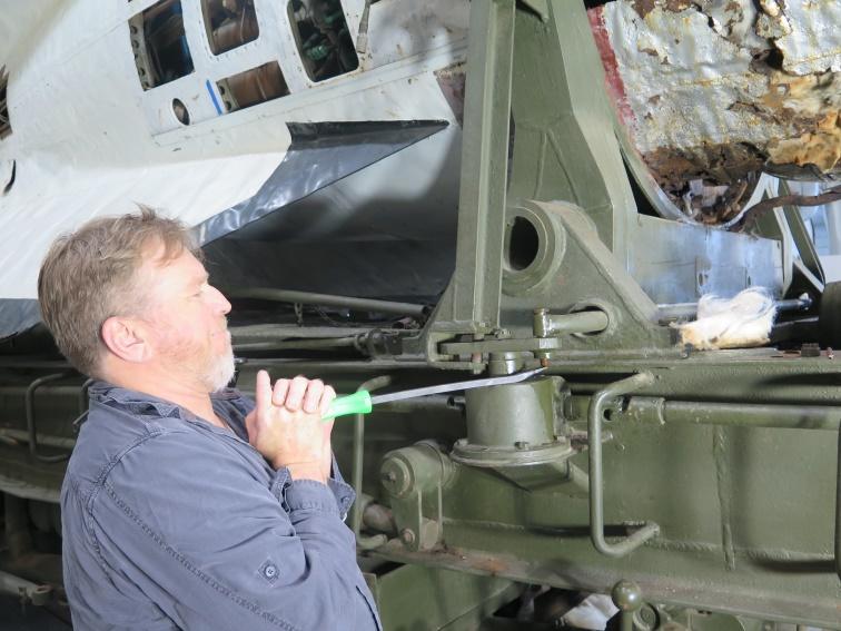
Image 15: Conservator removing split pins, nuts and locating pins
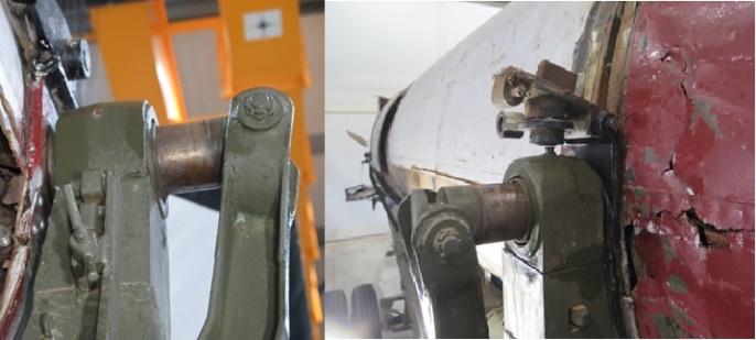
Image 16: Rear mount clamps levered away from V2
A section of significantly corroded original sheet metal skin located at the right rear of the centre section (image 17) had to be cut away to gain access to underside bulkhead bolts that connect the tail section due to the position of the V2 on the Meillerwagen and this section being unable to support the weight of the rocket if lifting was attempted (image 18).
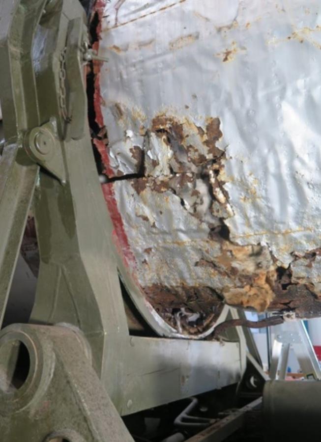
Image 17: Significant corrosion to steel sheet metal skin; access to underside bulkhead bolts restricted
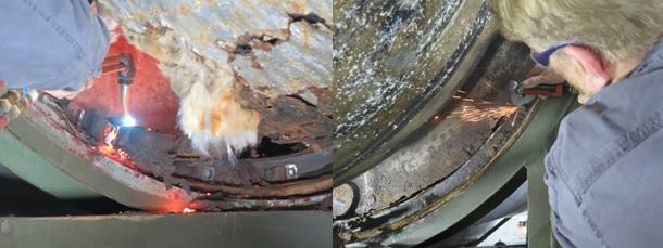
Image 18: Cutting rear centre section to gain access to bulkhead bolts
A cross brace lifting jig was manufactured and trial fitted (image 19). This would be used to lift the rear of the tail section and pull it away from the rocket (image 20).
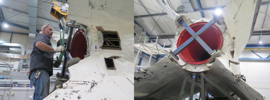
Image 19: Lifting jig trial fit

Image 20: Lift jig with tail puller fitted to rear tail section
The lifting rig was set up and connected to lifting points at the front and rear of the tail section. The tail section began to be separated, but the bulkhead connecting ring, which connects the tail and centre sections, would not release due to heavy corrosion (image 21). This was cut to release the tail section (image 22). With the tail section pulled away approximately 10 cm it was revealed that the engine mount was missing four top bolts. Bolts were put in place to lift the engine, which had been sagging inside the tail section, to a horizontal position. The non-original lower steel tail supports were cut away (image 23), giving the clearance needed for the tail section to be safely pulled away (image 24).
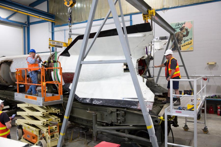
Image 21: Tail section lifting rig set up, bulkhead connecting ring not releasing
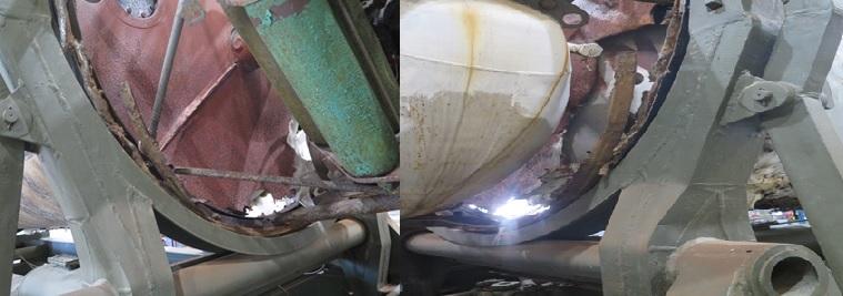
Image 22: Tail section bulkhead underside left and right side remains affixed due to corrosion and compaction
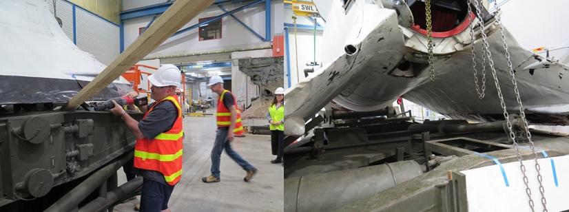
Image 23: Cutting lower non-original tail support with reciprocating saw, support removed

Image 24: Tail section safely removed from V2 rocket
The tail section was placed onto a temporary stand until its custom stand was ready (image 25).
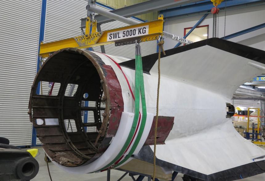
Image 25: Tail section placed onto its temporary stand
With the tail section removed, more paper tags were found naming different components of the engine. These were documented and removed (image 26).
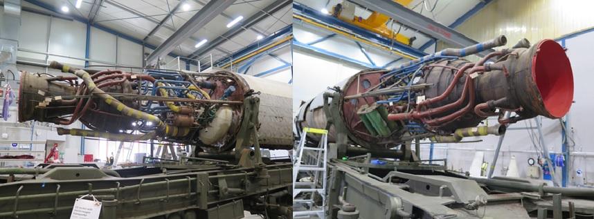
Image 26: V2 engine exposed showing paper tags naming engine components
The remaining support ring from the tail section was cut away to access the lower engine mount bolts (image 27). The lifting rig was set up and lower bolts were removed from the engine mount. The engine weight was taken and remaining bolts released (image 28). The engine separated easily from the centre section (image 29), and was lowered – standing vertically on railway sleepers as it would have been during the manufacture process – and cordoned off until its custom stand was ready (image 30 and 31).
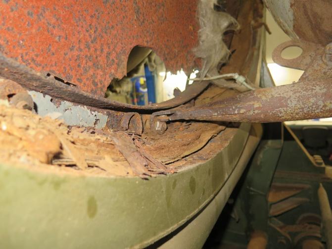
Image 27: Exposed lower engine mount and bolts

Image 28: Lifting rig set up weight of engine taken
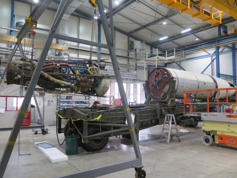
Image 29: Engine separated from centre section
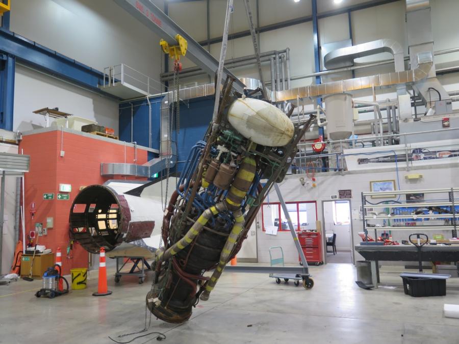
Image 30: Engine being lowered while sleepers are set up
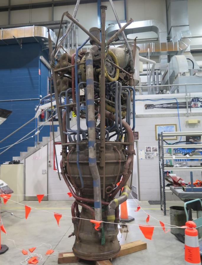
Image 31: Engine on sleepers
No explosive material was found in the V2 warhead. The integrity of the lifting rings attached to the warhead needed to be crack tested before these were used to lift the warhead. One ring was difficult to remove. Conservators applied heat to the lifting ring to loosen it, then Rost Off Plus was applied to lubricate and shrink the threaded portion of lifting ring. The second nose cone lifting ring screwed out easily with the application of Rost Off Plus. The rings were crack tested and put back in place. With a lifting rig set up (image 32), the warhead was lifted and a block was placed underneath the warhead and front support ring to avoid any crush injuries in the unlikely event the lifting equipment failed (image 33). The underside bolts were then removed (image 34).
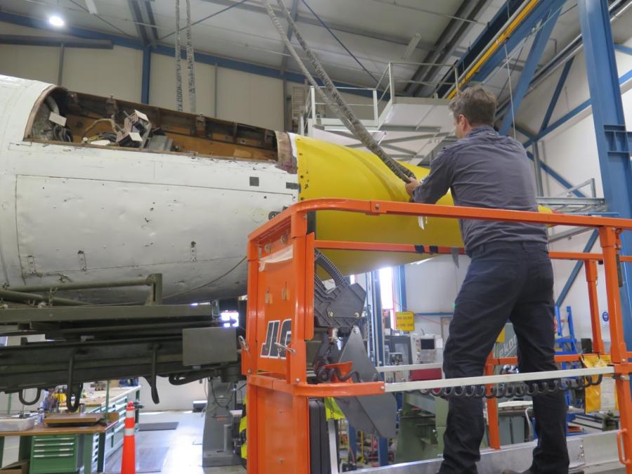
Image 32: Setting up the lifting rig
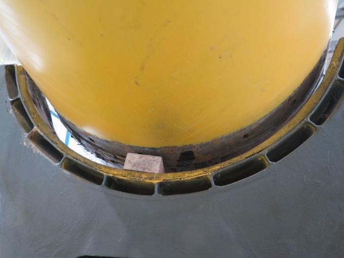
Image 33: Block placed underneath rocket
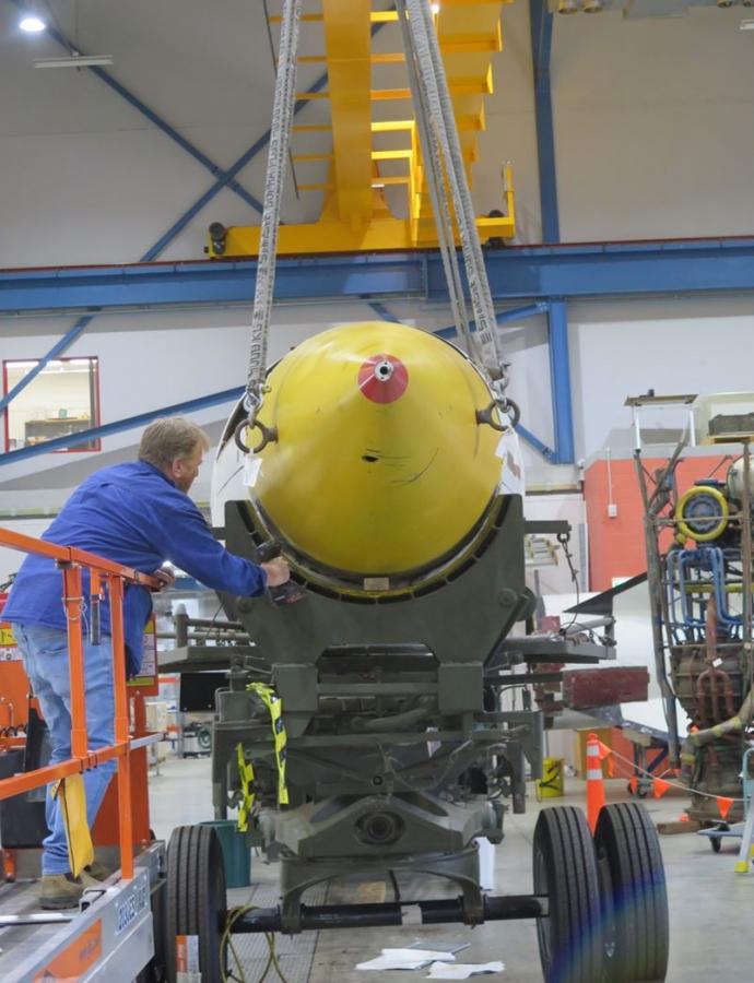
Image 34: Removing bolts from underside of the warhead
The warhead was lowered and the warhead lifting jig was set up to take weight. The upper bolts were removed and the warhead was lifted off. A forklift with pallet was placed underneath while being lifted as a precaution (image 35). The warhead remained level throughout the lift and lowered onto a pallet in an upright position.
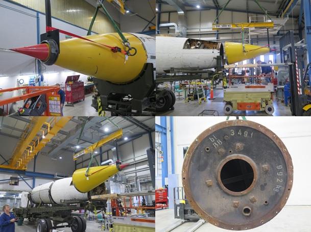
Image 35: Warhead lifting jig set up (top left), being lifted (top right), during lift (bottom left), rear of warhead during lift (bottom right)
To access the rods securing the control compartment to the centre section, the lower control compartment panels had to be removed. The lifting rig was set up and the rocket lifted slightly (image 36), the standing platform that folds out when the Meillerwagen is vertical was also removed in order to remove the lower control compartment panels (image 37). Once panels were removed and found to have debris and corrosion scale lining the walls (image 38) and more paper labels identifying components inside the control compartment (image 39). The debris was cleared and surfaces vacuumed and the labels were removed and kept safely. All nuts securing the rods were removed and the control compartment was lifted away from the rocket, blocks were placed on a pallet and control compartment placed on top of the blocks (image 40).
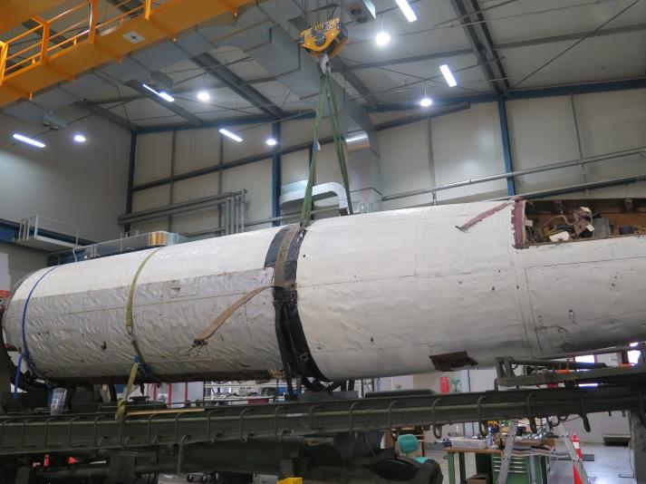
Image 36: Lifting rig set up to remove standing platform and lower control compartment panels
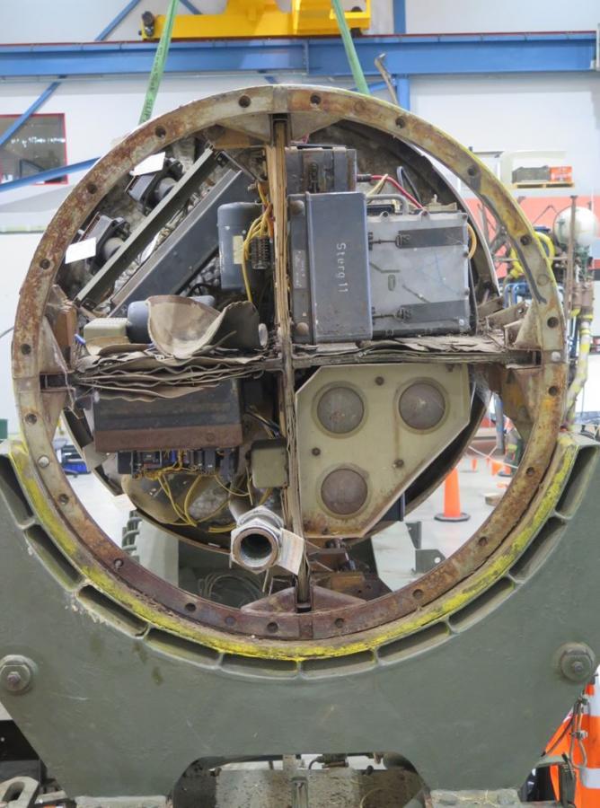
Image 37: Control compartment with all panels removed
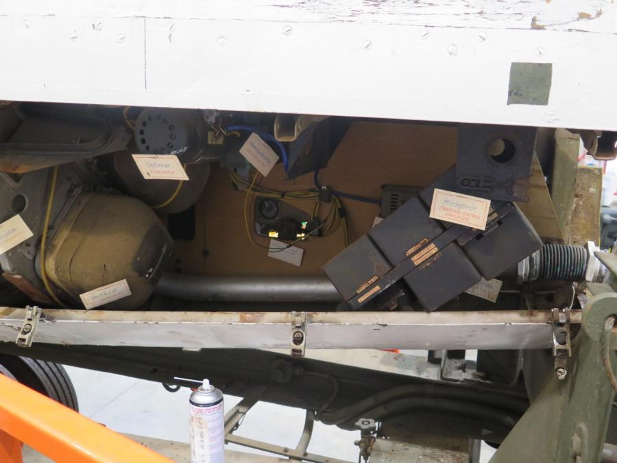
Image 38: Labels identifying components inside control compartment
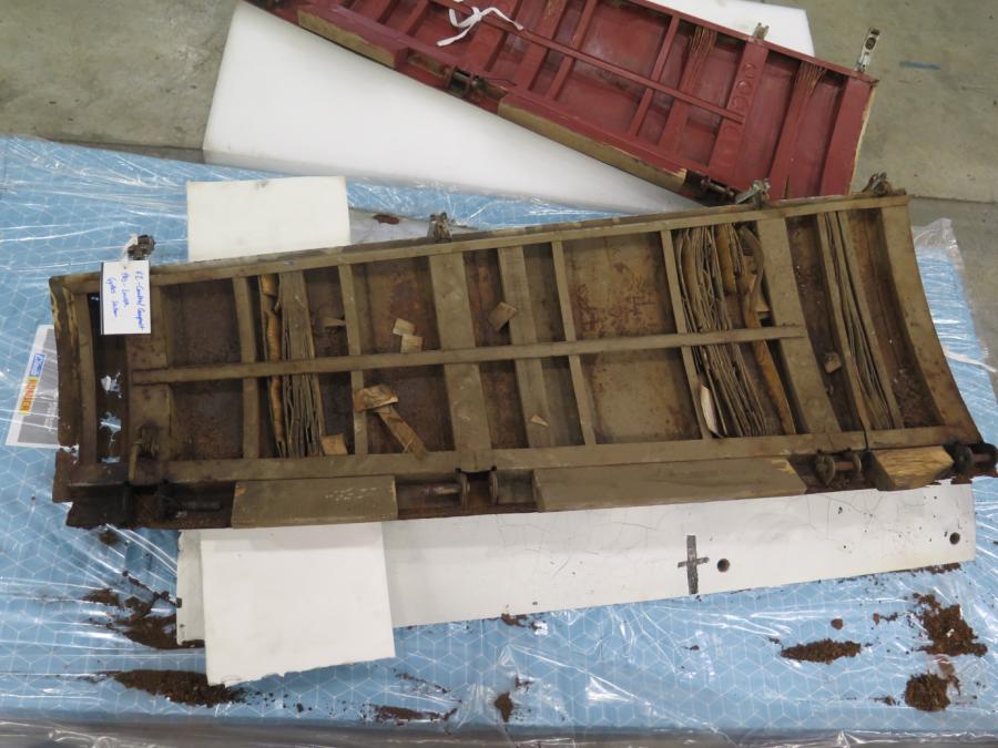
Image 39: Debris and corrosion scale inside panel walls
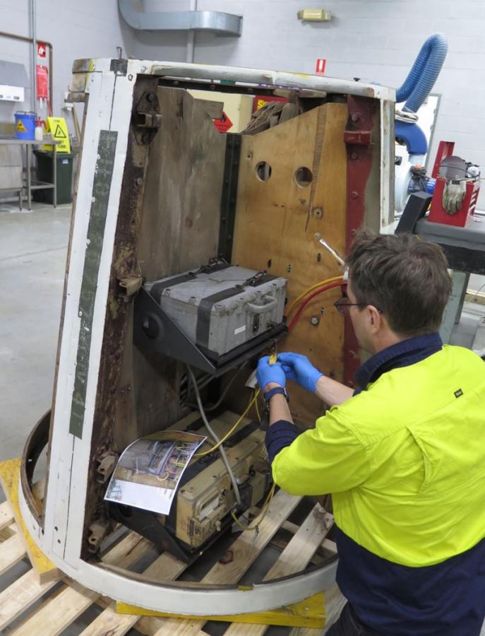
Image 40: Control compartment on pallet sitting on blocks
Investigations of the centre section showed differences in the skin. One section seemed smooth, unlike the wrinkled skin seen over the rest of the rocket (image 41 and 42). To see what was underneath, a section was removed revealing that a portion of the original skin had been cut away in the 1940s and 1950s (image 43). This was an unexpected discovery. The remaining smooth skin panels were removed, revealing that an extremely large section had been cut away, exposing the alcohol and oxygen tanks (image 44). The centre section will be taken off the Meillerwagen in early August 2021, attached to its custom stand and fully inspected.
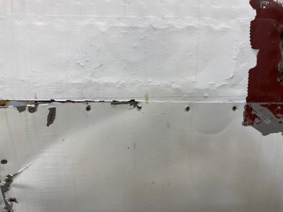
Image 41: Differences in skin texture wrinkled original skin on top, smooth non-original skin below
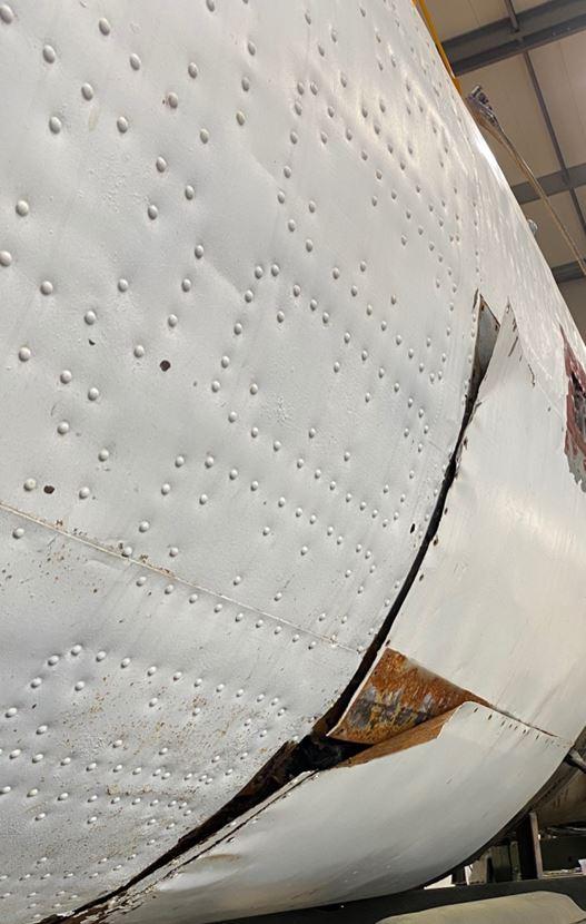
Image 42: Smooth skin panels peeling away from V2 shell
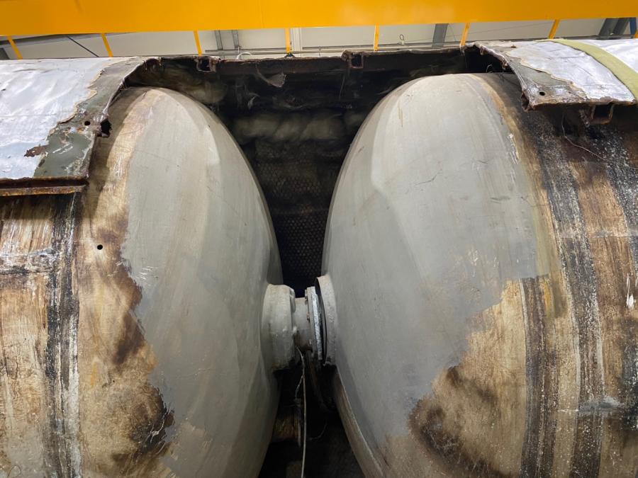
Image 43: Revealed section cut away when smooth skin was removed
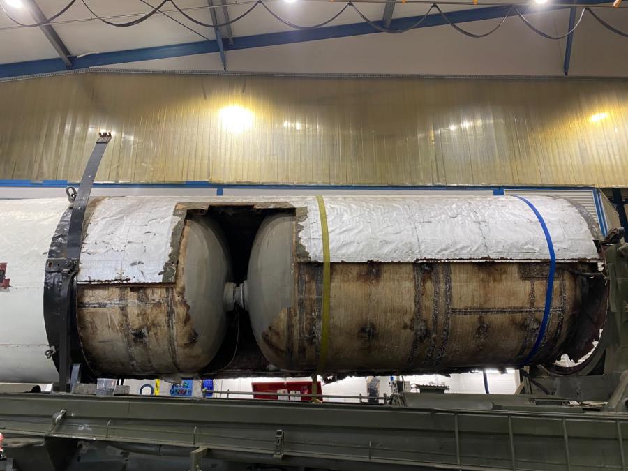
Image 44: Extent of original skin removed in the 1940s and 1950s
More updates will be available on the removal of the centre section from the Meillerwagen and the conservation treatments being undertaken on the different V2 components.